 dsale@topsfp.com
 español
 English
 русский
 العربية
 中文
中文



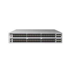
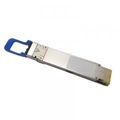
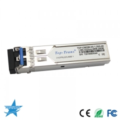
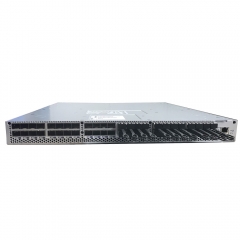
Selecting optical modules for an NVIDIA Spectrum switch is an end-to-end compatibility task. A transceiver is not chosen only by the number printed on the front label. The switch model, port cage, firmware, port speed and breakout mode, adapter or remote switch, fibre type, connector, reach, and power limit must work together. This guide provides a repeatable process for choosing optics for Spectrum-based Ethernet fabrics without relying on assumptions or generic “compatible” claims.
Identify the exact switch and port configuration
Begin with the switch model and hardware manual. Spectrum families and individual systems can use different cage types, such as SFP28, QSFP, QSFP-DD, QSFP112, or OSFP, and the supported speeds depend on the specific system and port mode. Some modern platforms can use native modules, splitters, or qualified adapters in defined configurations, but those options are not interchangeable across every port. Record the switch SKU, port number, cage type, intended operating speed, and whether the port is a native link, breakout, or management interface. This information should be present on every optics request for quotation.
Design the link as a pair
Compatibility must be checked at both ends. Identify the remote device: another Spectrum switch, a server NIC, a storage appliance, or an external router. Then compare protocol, speed, lane count, connector type, and media on both sides. A module that supports one speed in a switch does not make the remote port support that speed. For breakout links, verify the parent-port mode, the number of child links, the cable or optic mapping, and the software configuration. Record the complete path as a pair of approved endpoints and an approved interconnect rather than ordering two independent optics.
Choose the physical medium for the reach
DAC, ACC, AOC, and pluggable optics address different deployment conditions. Passive copper can be useful for short, well-managed in-rack runs. Active copper and active optical cables can simplify certain fixed-reach deployments. Pluggable multimode or single-mode optics provide flexibility when structured cabling, patch panels, or longer routes are required. Select the medium after measuring the path, including patching and cable-management distance, not just the straight-line distance between racks. Confirm fibre grade, connector polish, polarity, trunk or breakout arrangement, and the required number of fibres before installation.
Account for port power and thermals
High-speed optical modules can have meaningful power and cooling requirements. Spectrum hardware manuals identify supported interfaces and may designate high-power ports for certain optics. A transceiver that is electrically recognised can still be unsuitable if the port does not provide the required power or if the rack airflow design cannot sustain the module temperature. Check the switch’s approved port-power level, the optic’s maximum power specification, air direction, adjacent-port restrictions, and any need for blanking panels. Thermal validation is especially important when many high-rate optical modules are populated in the same chassis.
Use a controlled firmware and coding policy
Network operating system and firmware versions influence how a switch identifies, reports, and accepts transceivers. Keep the switch on an approved software baseline, and use current manufacturer documentation or a lab validation record for the module and version being deployed. Avoid treating a vendor name or EEPROM label as a complete compatibility test. For third-party optics, document the coding policy, test method, traceability requirement, and replacement process. A small sample validation should include insertion recognition, DOM telemetry where supported, link training, error counters, and a sustained traffic test at the intended speed.
Validate link budget and error behaviour
For optical links, a correct connector is not enough. Confirm the optical reach class, fibre type, insertion-loss budget, number of connections, and patch-panel arrangement. Clean and inspect connectors before testing; contamination can produce intermittent errors that look like a switch or module fault. After link-up, review FEC configuration, symbol or bit-error counters, flap events, and temperature telemetry where available. Test the link with representative traffic and record the results. This practice makes replacement and future expansion faster because the engineering team has a known-good reference.
Procurement checklist
- State the exact Spectrum switch model, port cage, port number, speed, and breakout mode.
- Name the remote device and its exact port capability.
- Specify media type, fibre grade, connector, polarity, route length, and patching.
- Confirm port-power and thermal suitability for the proposed optic.
- Validate a sample with the intended firmware before volume deployment and retain test records.
Avoid common compatibility mistakes
Do not mix a physical form factor with a protocol assumption, order an optic before confirming the remote endpoint, or use an unmeasured cable path for a reach decision. Do not populate a high-power module in a port that is not documented for it. Finally, do not change a module, switch firmware, and breakout configuration at the same time during troubleshooting. Change one variable, capture the result, and keep the final approved bill of materials under version control.
How to request a correct quote
Send the switch model, port mode, remote device, distance, fibre or cable preference, quantity, and desired delivery location. Topstar can help structure a compatible optical-module quotation, but the final selection should be approved against the current NVIDIA hardware manual, software compatibility information, and a test of the exact end-to-end link.
